
Hi Paul,
Here's some info that I hope helps. First of all Cat introduced the D7E in 1963. The D7E was a larger machine than the old D7. The old D7 3T&17A size machine was replaced by the new larger D6C. The old D6 9U size machine was replaced by the new D5, a designation which had not been used in years. Madness you say? Well, see the Cat machine designations of the recent past!
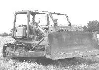
The D7E parts will not work on your machine. The photos of the hard- nose and rams on 657bruce's machine seem to be from a D6C. The D6C used internal relief valves on the rams. From the photos it looks like 657bruce used a Bee Gee external pump. Those old Bee Gee's were fairly plentiful and parts are still available. The Bee Gee would be a easy fix but I do not know how well it performs as a blade control. I do not know why 657bruce did not respond to your post, maybe try a private message? Let me know.
The 17A D7 used a larger hyd. tank than the 3T D7 and uses a "pooched-out" lower grill.
yeah thanks for the replys fellas seiscat had sent bruce a pm and he did reply and told me he used a D7 E nose cone and a beegee pump the nose cone was cut done around 3 inchs in the width.
So does any body no what volume of oil was used by the D7 E and do the rams off a D7 E have the relief valve inside them
thanks Paul
Wow! I was fooled on this one! What got me thinking D6C was the rams not having a tube running the entire length of the top side of the ram which is the case on the D7E. Evidently 657bruce rolled the rams over to protect the tubes. Dang, that is embarrassing for someone that owns a hyd. blade D7E!
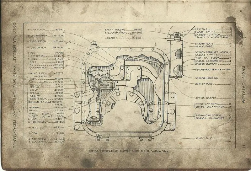
I have been looking at my hyd. controls parts book for my D7E and the specification for all arrangements is 54 U.S. gallons per minute. The pressure relief valve is mounted inside the hyd. tank.
The D7E used three hyd. controls the 171, 172 and 173. The 171 arrangement was run off the transmission pump and was intended to run a hyd. tilt cylinder on a cable blade machine. The 172 arrangement had a pump mounted on the accessory drive on the rear of the engine and the tank mounted on the floorboard to the operator's right. The 173 arrangement had the pump driven by the front of the crankshaft and the tank mounted behind the lower half of the radiator grill.
I hope this helps. I've got to go scrape all this egg off my face now.👍
Wow! I was fooled on this one! What got me thinking D6C was the rams not having a tube running the entire length of the top side of the ram which is the case on the D7E. Evidently 657bruce rolled the rams over to protect the tubes. Dang, that is embarrassing for someone that owns a hyd. blade D7E!
I have been looking at my hyd. controls parts book for my D7E and the specification for all arrangements is 54 U.S. gallons per minute. The pressure relief valve is mounted inside the hyd. tank.
The D7E used three hyd. controls the 171, 172 and 173. The 171 arrangement was run off the transmission pump and was intended to run a hyd. tilt cylinder on a cable blade machine. The 172 arrangement had a pump mounted on the accessory drive on the rear of the engine and the tank mounted on the floorboard to the operator's right. The 173 arrangement had the pump driven by the front of the crankshaft and the tank mounted behind the lower half of the radiator grill.
I hope this helps. I've got to go scrape all this egg off my face now.👍
Gets messy,
Under the 172 & 173 hydraulic control there is a carry over of the front mounted pump/control S/N 48C at 100 gpm (#173 being similar to #46 hydraulic control) similar to the 100gpm unit used on the 3T and 17A.
The cylinders used prior to 47A3396 and 48A6393 are similar construction to the 3T & 17A with no quick drop valves in the cylinder head.
The no drop valve cylinders are 6" bore x 37.625 stroke part # 3J4783. These cylinders have the center mount trunions.
For comparison, the higher presure quick drop cylinders are 4.75 " diameter.
I am looking at my Caterpillar hydraulic controls parts book for serial numbers 48C1-up, 24G1-up, 25G1-up, 65G1-up and 67G1- up and it lists all arrangements to be 54 U.S. gallons per minute except the 171 arrangement which received oil from the transmission pump to operate a hydraulic tilt cylinder on a cable blade machine at 17 U.S.gallons per minute. There is no arrangement listed which requires more than 54 U.S. gallons per minute.
The serial numbers listed by old magnet are the break between 160 and 180 hp machines and have nothing to do with quick-drop valves.
I have a high regard for your knowledge old magnet, but you are mistaken on this.
I have form #35279.
Look at the bottom of page #7, arrangement 2J5913 which is a 100 gpm unit that takes you to page #12 for the 48C control group.
Yes it is confusing as the listings start out with the 54 gpm units.
You have to go to form #UE035033 for the 7A, 7S, 7U Bulldozers to get the info on the cylinders. S/N's 72F1-up, 59F1-up, 42G1-up.
I can post if required.
I am not sure if those s/n breaks define whether or not the non quick drop cylinders extend past those numbers or not but they would be required to match the 48C hydraulic control.
I give up, how can I make so many mistakes so fast. I also have form 35279 and in my rush to show off my knowledge and resources I overlooked the bottom of page 7 which does indeed list a 100 U.S. gallon per minute arrangement.
My hat is in my hands old magnet and I hope you can forgive my arrogance.


Our channel highlights machines from the earliest Holt and Best track-type tractors, equipment from the start of Caterpillar in 1925, up to units built in the mid-1960s.
Chapter Nineteen
| Wheatlands Warracknabeal Agricultural Museum 34 Henty Highway, Warracknabeal 3393Chapter Nineteen
| 1234 Carngham - Lake Goldsmith Road Lake Goldsmith VIC 3373Chapter Two
| Folds Farm, Godshillwood, Fordingbridge, Hampshire, SP6 2LU
Antique Caterpillar
Machinery Owners Club
1115 Madison St NE # 1117
Salem, OR 97301
Terms & Privacy
Website developed by
AdCo
"I also joined a year ago. had been on here a couple of times as a non-member and found the info very helpful so I got a one year subscription (not very expensive at all) to try it out. I really like all the resources on here so I just got a three year. I think its a very small price for what you can get out of this site."
-Jason N